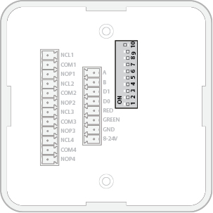
Details for the Wiegand interface signals:
DIP |
Abbr. |
Description |
|---|---|---|
10 |
INT/EXT |
Internal/external antenna |
9 |
Not used |
|
8 |
TERM |
Not applicable for Wiegand. Set to OFF. |
7 |
UP |
Not applicable for Wiegand. Set to OFF. |
6 |
DOWN |
Not applicable for Wiegand. Set to OFF. |
5 |
A4 |
ON = Starts in pairing mode. OFF = Normal use. |
4 |
A3 |
Controls byte order of transmitted credentials. OFF => The byte order is left as is. ON => The byte order is reversed compared to what is received as input to the Hub Wiegand EAC interface component. |
3 |
A2 |
Controls addition of parity bits on transmitted credentials. One even parity bit before and one odd parity bit after the actual credentials. OFF => Addition of parity is disabled. Credentials are transmitted as received. ON => Addition of parity bits is enabled. |
2 |
A1 |
Set to OFF. Reserved for future use. |
1 |
A0 |
Controls use of Red LED signal for access decision. ON = Red LED is used. OFF = Red LED is ignored. |