The DIP 1-5 has two functions, either automatic paring mode, or manual selection of EAC address on the RS485. Default configuration is to select an address according to below. By doing so automatic pairing will be deactivated.
DIP 1-5 – Pairing mode
If DIP 1-5 are set to OFF, pairing mode will be activated. This means that after powering on the communication hub it will automatically try to pair with locks within range. Automatic pairing will only be made with unpaired locks. The automatic pairing procedure is described in ref [2], Aperio Online Programming Application manual.
DIP 1-5 – Selecting EAC address
It is possible to select an address 1-31 for the AH15 communication hub using the DIP switch. For mixed modes, see section "Selecting the correct EAC address (AH15/AH30)"Selecting the correct EAC address (AH15/AH30) for more details and advance options.
Select a unique EAC address 1-15 for each communication hub by use of the DIP switch according to the table below. (The resulting lock addresses for each communication hub address are shown to the right):
DIP 4 – DIP 1 |
AH30 Hub address |
Lock addresses |
|---|---|---|
0000 |
Reserved |
|
0001 |
0x01 |
0x01, 0x11, 0x21, 0x31, 0x41, 0x51, 0x61, 0x71 |
0010 |
0x02 |
0x02, 0x12, 0x22, 0x32, 0x42, 0x52, 0x62, 0x72 |
0011 |
0x03 |
0x03, 0x13, 0x23, 0x33, 0x43, 0x53, 0x63, 0x73 |
0100 |
0x04 |
0x04, 0x14, 0x24, 0x34, 0x44, 0x54, 0x64, 0x74 |
0101 |
0x05 |
0x05, 0x15, 0x25, 0x35, 0x45, 0x55, 0x65, 0x75 |
0110 |
0x06 |
0x06, 0x16, 0x26, 0x36, 0x46, 0x56, 0x66, 0x76 |
0111 |
0x07 |
0x07, 0x17, 0x27, 0x37, 0x47, 0x57, 0x67, 0x77 |
1000 |
0x08 |
0x08, 0x18, 0x28, 0x38, 0x48, 0x58, 0x68, 0x78 |
1001 |
0x09 |
0x09, 0x19, 0x29, 0x39, 0x49, 0x59, 0x69, 0x79 |
1010 |
0x0A |
0x0A, 0x1A, 0x2A, 0x3A, 0x4A, 0x5A, 0x6A, 0x7A |
1011 |
0x0B |
0x0B, 0x1B, 0x2B, 0x3B, 0x4B, 0x5B, 0x6B, 0x7B |
1100 |
0x0C |
0x0C, 0x1C, 0x2C, 0x3C, 0x4C, 0x5C, 0x6C, 0x7C |
1101 |
0x0D |
0x0D, 0x1D, 0x2D, 0x3D, 0x4D, 0x5D, 0x6D, 0x7D |
1110 |
0x0E |
0x0E, 0x1E, 0x2E, 0x3E, 0x4E, 0x5E, 0x6E, 0x7E |
1111 |
0x0F |
0x0F, 0x1F, 0x2F, 0x3F, 0x4F, 0x5F, 0x6F, 0x7F |
The following figure shows an example of a default installation.
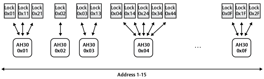
Address allocation in a default installation